1

Let's say I have a particle moving with some velocity $\mathbf{U} = (u,v,w)$, and I can measue a 2D projection of this motion to get $\mathbf{U_{1}} = (u_{1},v_{1})$. One way to estimate the third component would be to image the same particle motion from a different angle.

I then measure $\mathbf{U}$ "from a different plane", rotated by $\alpha, \beta, \gamma \neq N\times90$ about the origin of $\mathbf{U}$ (so both projected vectors have the same origin) and get $\mathbf{U_{2}} = (u_{2},v_{2})$. I know the angles of rotation to align the two planes (and by rotating, say $\mathbf{U_{2}}$ onto the plane of $\mathbf{U_{1}}$ I can get a third component from using the rotation dot product, however, it seems to me that this will only give me a "projected" third component, instead of the "true" component. Writing this question and thinking about it, it's probably not possible to obtain the "real" third component (unless the second measurement was taken at 90 degrees along one axis).

TL;DR

Given an unknown vector $\mathbf{U} = (u,v,w)$, with a known projection $\mathbf{U_{1}} = (u_{1},v_{1})$ in one plane, and another known projection $\mathbf{U_{2}} = (u_{2},v_{2})$ at a different plane rotated around the origin of $\mathbf{U}$ by $\alpha, \beta, \gamma \neq N\times90$ is it possible to obtain $\mathbf{U} = (u,v,w)$?

Potentially similar question, but they wory about scaling and it's only rotation in 2D (I think) How to transform a set of 3D vectors into a 2D plane, from a view point of another 3D vector?

leb
  • 45
  • The two projections define a pair of lines through $\mathbf U$. Mathematically, you have enough information to recover $\mathbf U$. In practice, small perturbations in the measurements of the projections will cause the two resulting lines not to intersect. – amd Sep 25 '17 at 19:39
  • Yes, the "real lab" uncertainties would prevent a perfect match (I interpret the intersecting lines as a common point of origin), but I had hoped that it would be good enough for a local estimation given some calibration. Perhaps you could point me into the direction of the technique applicable here (it's been some years since I used linear algebra...)? – leb Sep 26 '17 at 10:37

1 Answers1

3

[I’m changing the notation slightly from that in the question. Uppercase symbols represent points/vectors in 3-D, and lowercase points/vectors in 2D.]

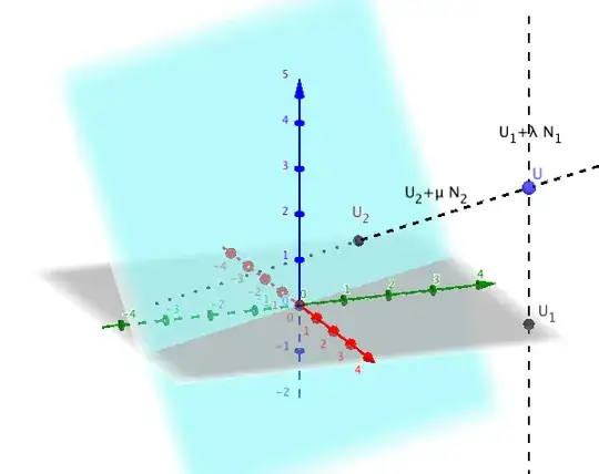
This is a fairly straightforward triangulation problem. Let $\mathbf N_1$ and $\mathbf N_2$ be then normals of the planes $\mathbf\pi_1$ and $\mathbf\pi_2$. If $\mathbf U_1$ and $\mathbf U_2$ are the projections of $\mathbf U$ onto these two planes, their back-projections are the lines $\mathbf U_1+\lambda\mathbf N_1$ and $\mathbf U_2+\mu\mathbf N_2$. $\mathbf U$ lies at the intersection of these lines.

enter image description here

In theory, you just have to compute this intersection to find $\mathbf U$. In practice, for the lines to intersect they must be coplanar and even a small perturbation to $\mathbf U_1$ or $\mathbf U_2$ will destroy this coplanarity. A straightforward way to get an estimate for $\mathbf U$ is to take the midpoint of the points of closest approach of the two lines. You can find a description of this fairly standard computation in this answer by marty cohen and many other places here and elsewhere on the Internet. (Of course, if $\mathbf\pi_1$ and $\mathbf\pi_2$ are two of the coordinate planes, you can just read the coordinates of $\mathbf U$ directly.)

If this estimate isn’t accurate enough, a more sophisticated approach is to find the smallest adjustment (in image space) to $\mathbf U_1$ and $\mathbf U_2$ that makes their back-projections coplanar. This is covered in detail in $§14.4$ of Hartley and Zisserman’s Multiple View Geometry In Computer Vision. I’ll just give the formula here; see the book for full details.

Given the correspondence $(u_1,v_1)\leftrightarrow(u_2,v_2)$ between a pair of points on the respective image planes, we want to find $(\hat u_1,\hat v_1)$ and $(\hat u_2,\hat v_2)$ such that $(u_1-\hat u_1)^2+(v_1-\hat v_1)^2+(u_2-\hat u_2)^2+(v_2-\hat v_2)^2$ is minimized. W.l.o.g. we can take $\mathbf\pi_1$ to be the $u$-$v$ plane, so that its camera matrix is the canonical $$P_1=\begin{bmatrix}1&0&0&0\\0&1&0&0\\0&0&0&1\end{bmatrix}.$$ This just picks out the $u$- and $v$-coordinates of $\mathbf U$. The projection matrix onto $\mathbf\pi_2$ will have the form $$P_2=\left[\begin{array}{c|c}M_{2\times 3}&\mathbf t\\\mathbf 0^T&1\end{array}\right].$$ The point $\mathbf U$ then satisfies the linear equations $P_1\mathbf U =\mathbf u_1=(u_1,v_1)$ and $P_2\mathbf U = \mathbf u_2=(u_2,v_2)$.

The affine fundamental matrix of this epipolar configuration is $$F_A=\begin{bmatrix}0&0&a\\0&0&b\\c&d&e\end{bmatrix}$$ where $$a = m_{23} \\ b=-m_{13} \\ c=m_{13}m_{21}-m_{11}m_{23} \\ d=m_{13}m_{22}-m_{12}m_{23} \\ e=m_{13}t_2-m_{23}t_1.$$ (In your case, where $P_2$ has no translation component, we would have $e=0$.) The adjusted coordinates are then given by the formula $$\begin{bmatrix}\hat u_2 \\ \hat v_2 \\ \hat u_1 \\ \hat v_1\end{bmatrix} = \begin{bmatrix}u_2 \\ v_2 \\ u_1 \\ v_1\end{bmatrix}-{au_2+bv_2+cu_1+dv_1+e\over a^2+b^2+c^2+d^2}\begin{bmatrix}a\\b\\c\\d\end{bmatrix}.$$ (You might recognize this as the result of a standard least-squares fit, which itself is basically a projection onto a hyperplane in $\mathbb R^4$.) With these adjusted coordinates in hand, you can then find the intersection of their back-projections in the ways described previously.

amd
  • 55,082
  • Thank you for taking the time to explain this, however, I do not understand what you mean when you say that U will lie on the intersection of those two lines (I assume lambda and mu are just arbitrary variables you chose without any meaning in linear algebra) or more precisely, I do not see how this will give me U. Anyway, I'm not able to obtain the book at the time, so I tried looking into directional cosines, which led me to looking at Euler angles, and that's a entirely new can of worms. – leb Sep 27 '17 at 13:20
  • From searching around it seemed that I should be able to obtain directional cosine matrix by simply combining the rotation matrices (around x, y, and then z axis) using the angles that I was able to align my planes (or volumes in my case, which I mentioned in the question). However, using the approach described in "Conversion between multiple Cartesian bases" [https://en.wikipedia.org/wiki/Euclidean_vector#Multiple_Cartesian_bases] gave inconsistent results for the third component, I believe that my volume alignment was most likely not good enough. – leb Sep 27 '17 at 16:41
  • Actually, it seems that Tait-Bryan angles might be much closer to what I need. I think I'll have to try their XYZ or ZYX rotation matrices to see what happens. – leb Sep 27 '17 at 18:42
  • @v.z. Sounds to me like you’re having trouble just defining the second projection plane. – amd Sep 27 '17 at 21:12
  • unless I have completely forgotten lin.alg. I think I can assume that I have 3 "points" for each plane (common origin), however, it was not clear to me what did you mean about the vector U being on the intersection point (as in is that the end of the head of the vector which originates from the common origin?). Anyway, I went back at looking at directional cosines (sorry if it's annoying I'm not able to follow your train of thought) since I reckoned simply rotating one basis to another with 3 rotation matrices would give me the directional cosines, leading to a trivial solution. – leb Sep 27 '17 at 21:39
  • I just noticed you added a figure - much appreciated! Would you mind sharing the software you were using for this? – leb Sep 27 '17 at 21:40
  • @v.z. I used GeoGebra for that. BTW, $\lambda$ and $\mu$ are just the parameters in the parametric equations of the two lines. You might be more used to seeing $t$ and $s$ used for this. – amd Sep 27 '17 at 21:48
  • Playing around with GeoGebra myself and thinking about what you said everything finally made perfect sense geometrically. Now all I have to do is solve those pesky linear algebra equations!

    However, it does seem non trivial defining the second plane, because it needs to be expressed in the basis of the first one, and despite the fact I have all the rotations to align the 3d volumes, it seems that there has to be a specific sequence to do that.

    – leb Sep 28 '17 at 18:17
  • @v.z. That’s right. Rotations about different axes don’t commute, so you do have to take some care with the order in which they’re applied. It might be easier to construct the final rotation directly, depending on what you have to work with: make the plane’s normal the image of the $z$-axis and pick a unit vector in the plane to be the $x$-axis image. These choices completely determine the rotation: the image of the $y$-axis must be their cross product. It might be worth posting a separate follow-up question for this sub-problem, although similar ones have been asked here many times. – amd Sep 28 '17 at 18:31
  • @v.z. It’s also quite easy to construct a reflection that maps the $z$-axis onto an arbitrary plane normal (see here). That might be good enough for this computation. – amd Sep 28 '17 at 18:33