4

I am a physics graduate student and I want to create some 3D models for my crystal samples. We have an X-ray diffractometer in our lab. It comes with a goniometer inside it, so basically I can take as many photos as needed from any angles. (I have included a gif animation made of 10 photos taken by the machine as an example below)

a gif animation made of ten photos taken by the machine

My problem is, given these 2D photos, am I able to construct 3D models for my crystals in AutoCAD or similar software so that I can determine angles, edge lengths and volume more precisely.

I am new to 3D printing section. I just thought maybe someone here has encountered with a similar problem. It would be very helpful if anyone could tell me any Github codes, MATLAB scripts, Mathematica scripts or software that can finish this kind of job. I can try to figure it out myself.

0scar
  • 37,708
  • 12
  • 68
  • 156

3 Answers3

3

YES, it is possible to make a model from several shots, if you know the angle of rotation between the pictures.

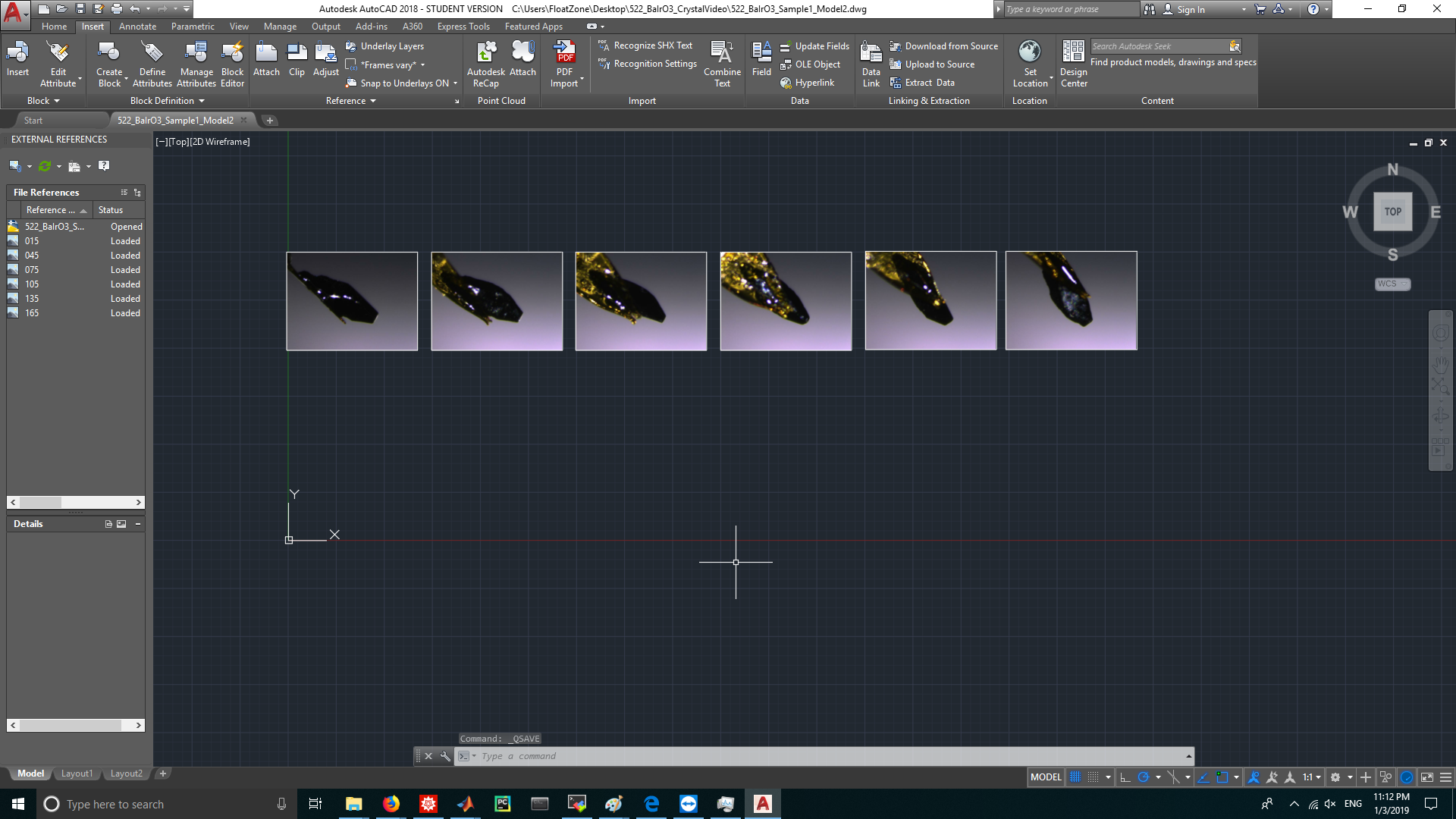
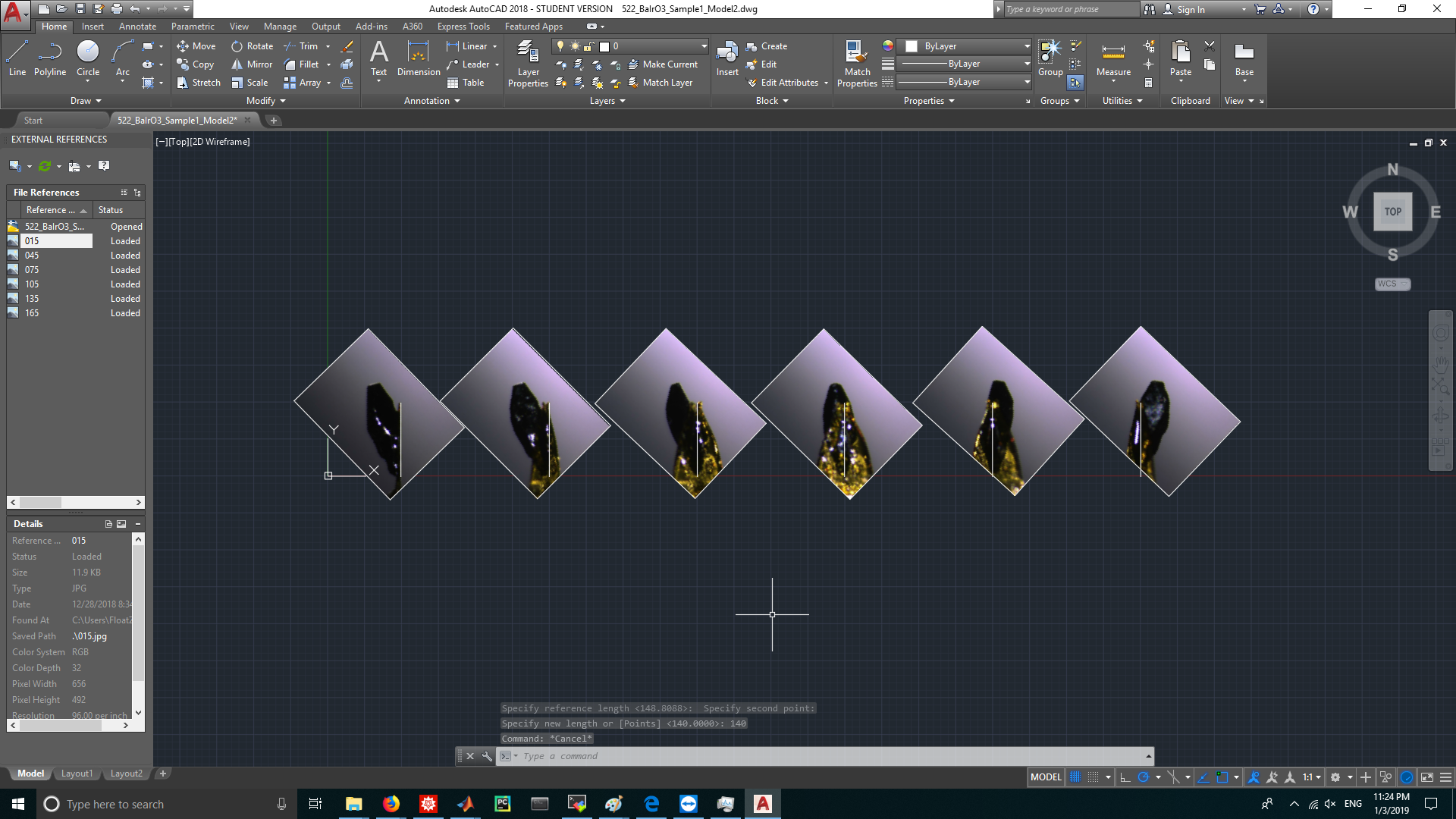
most CAD programs allow to insert a picture, for example as backdrop or to trace it. We are interested in the later use:

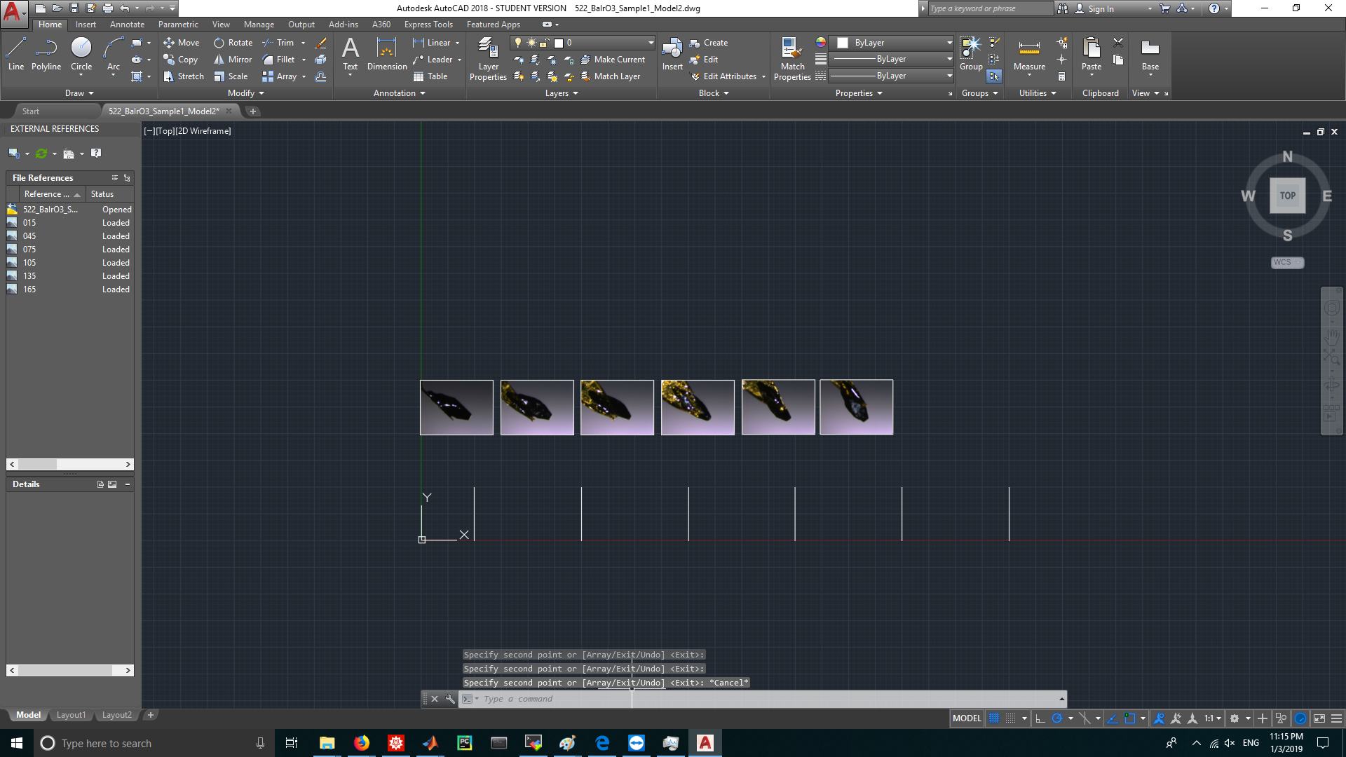
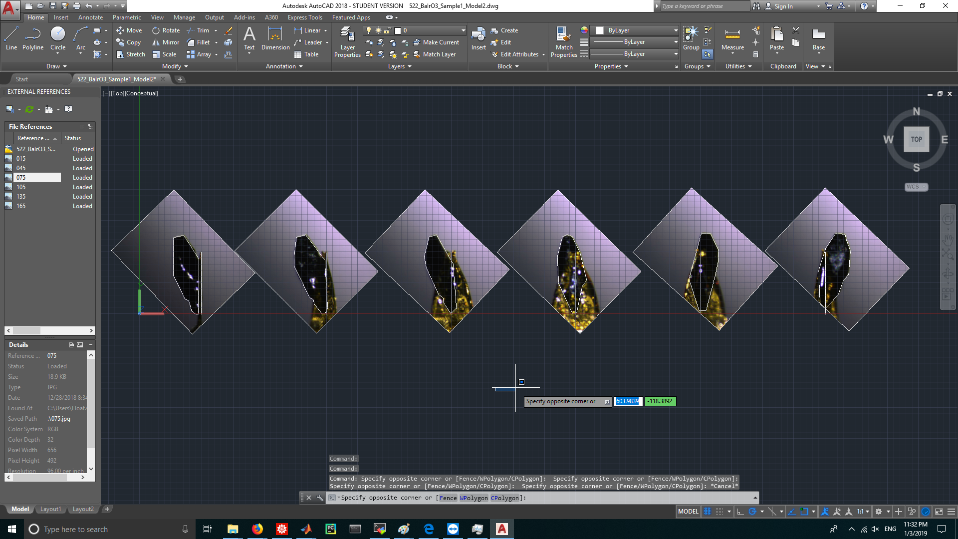
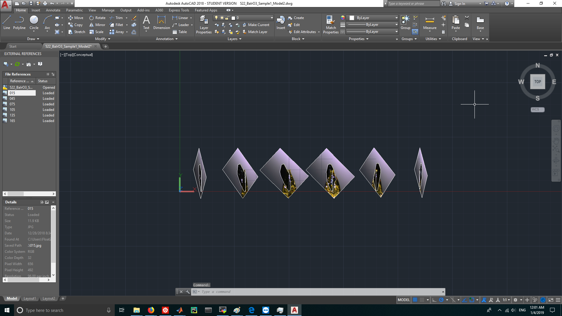
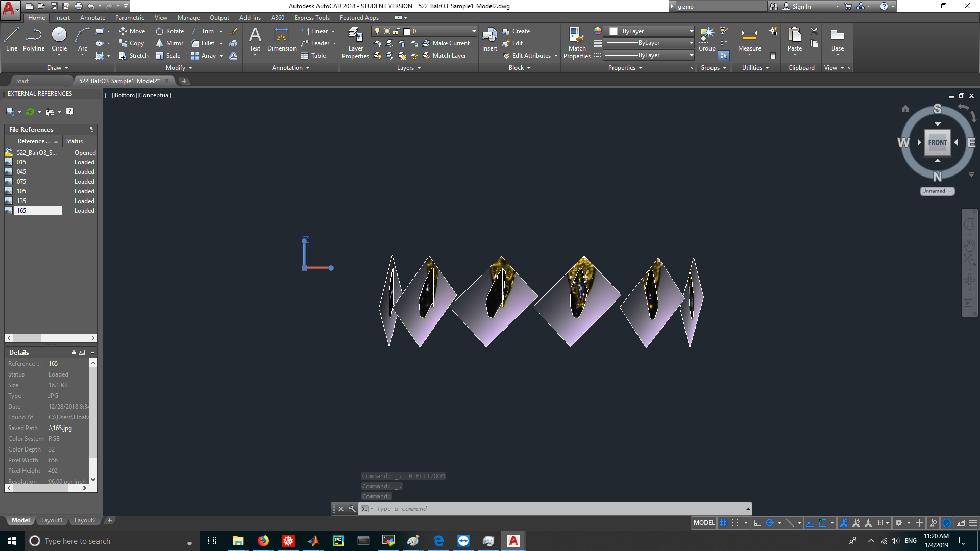
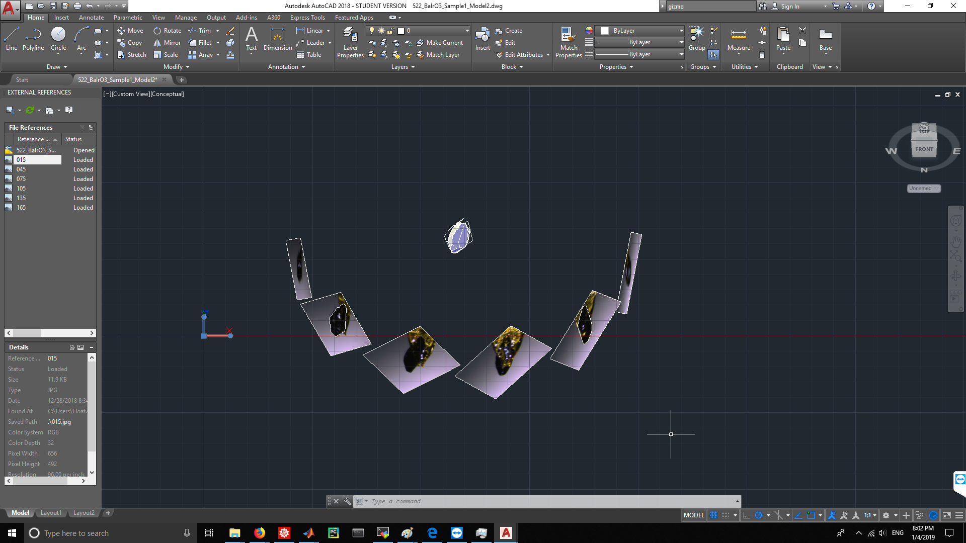
We insert the picture, trace it in the picture's layer, then insert the next picture, rotated around the axis of rotation of the picture, and trace that. This we repeat again and again. The resulting cloud of outlines approximates the photographed body to a good degree.

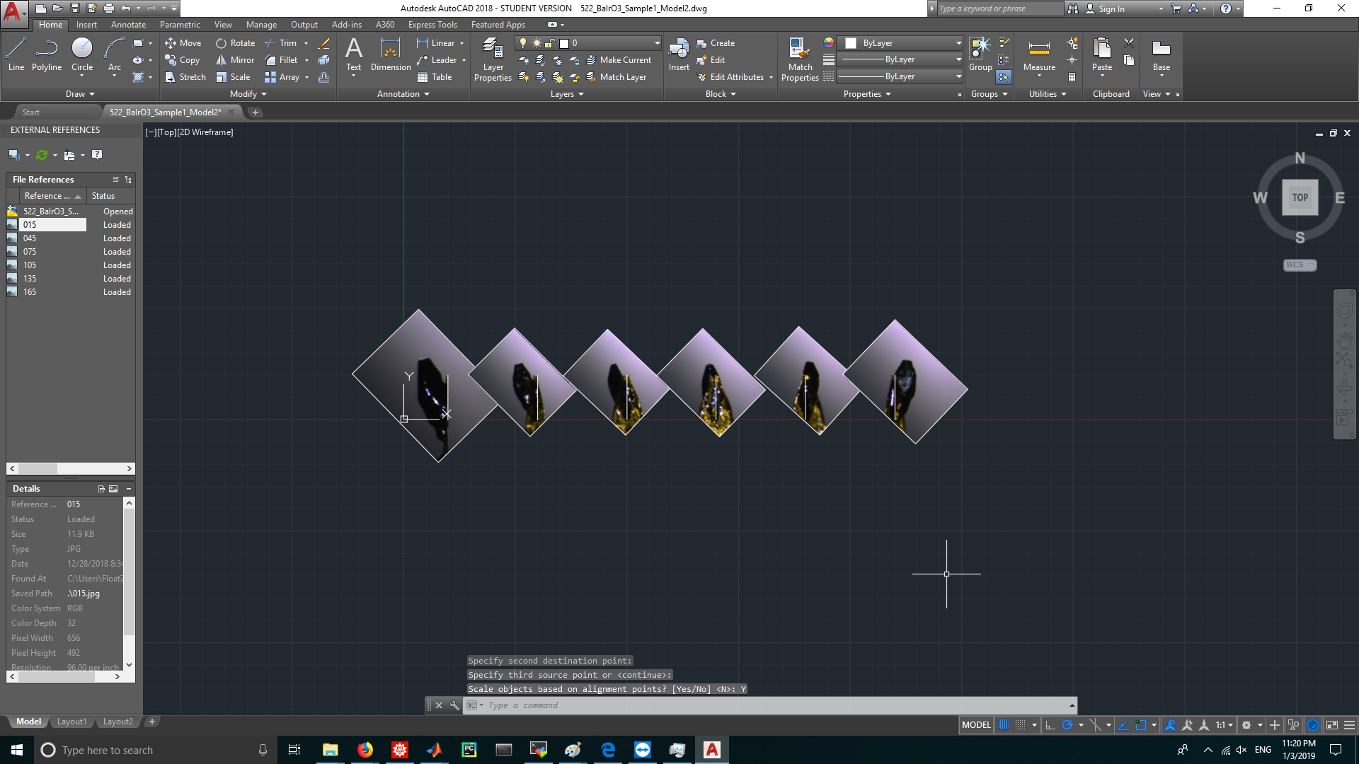
There is a big caveat though: all photos must be in the same scale and distance, the rotation of the object has to be around one axis of the item itself (no wobble) and the rotation between the pictures has to be known quite exact. This principle is pretty much used by raster scanning by the way.

With a very hard contrast between the crystal and the backdrop, software might be able to automate the tracing process (for example use a white background and a black crystal and make sure no reflection hits the camera).

Example using Fusion360

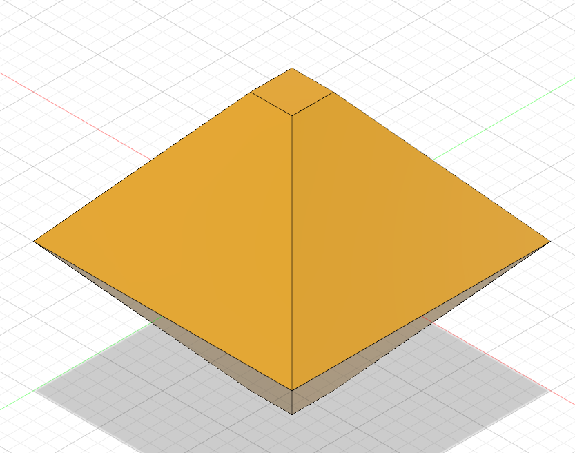
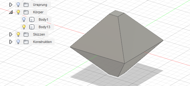
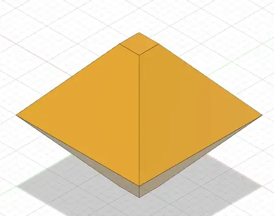
Let's assume I have a perfect crystal like this octahedron with two cut tips Octahedron with upper and lower tip cut

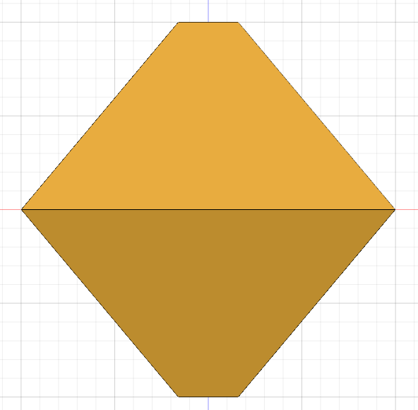
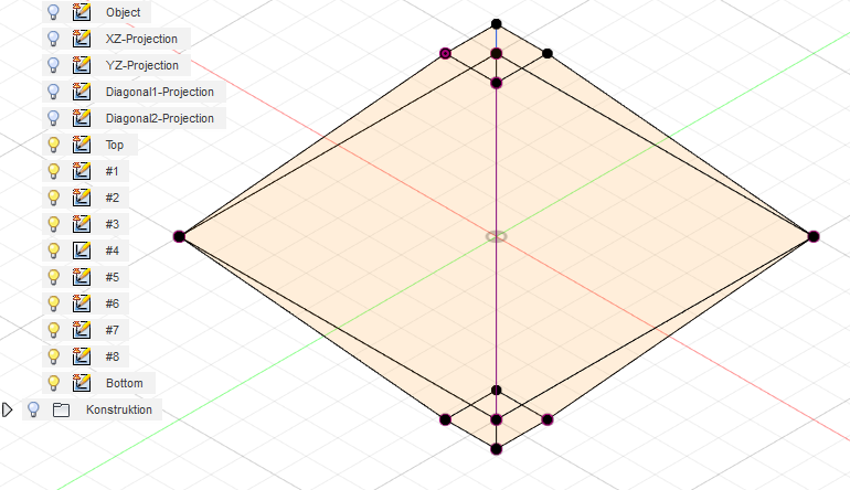
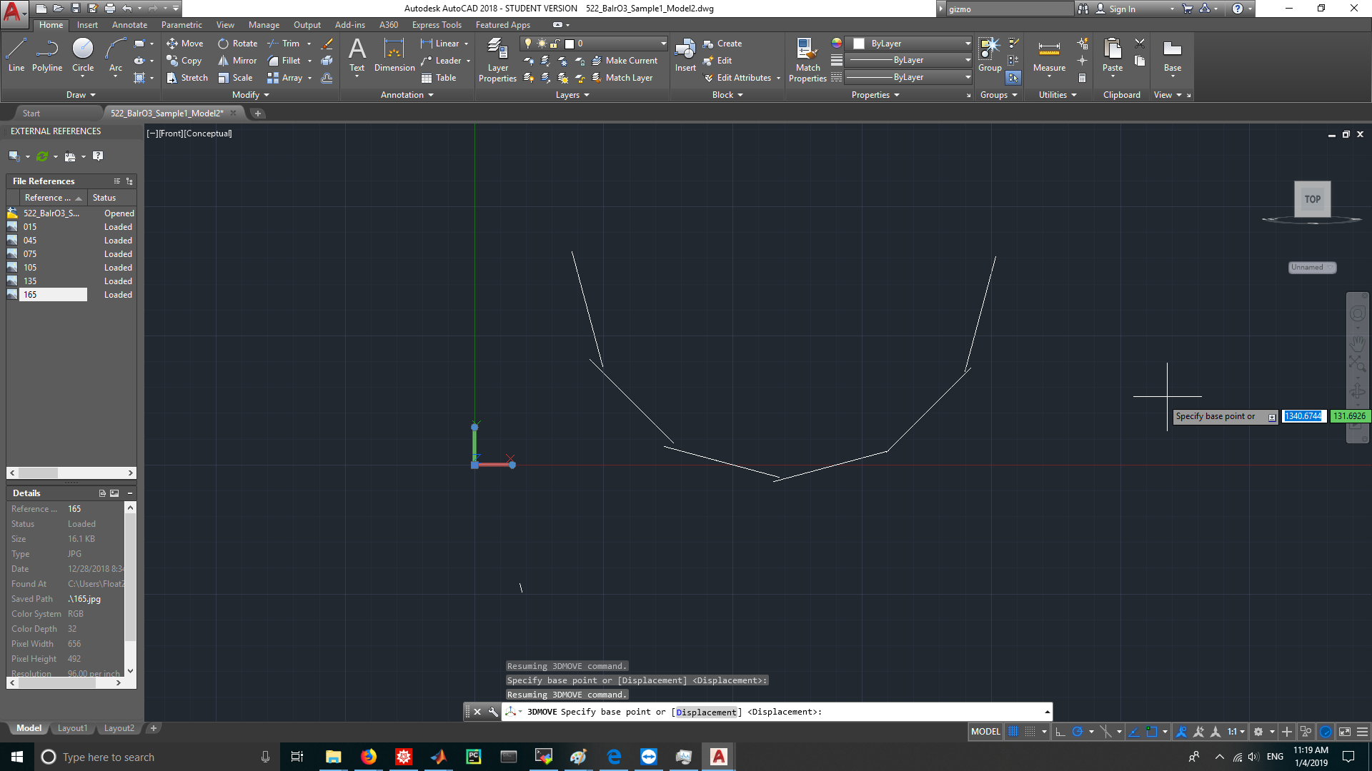
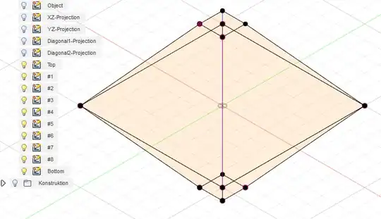
To model this, we need at least a photo of the XZ and YZ shape (that is, 90° rotation to each other), which look like this:

XZ and YZ plane projectionThe outlines traced

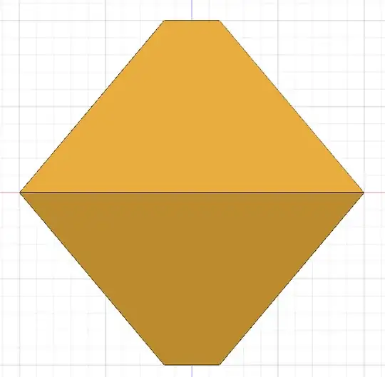
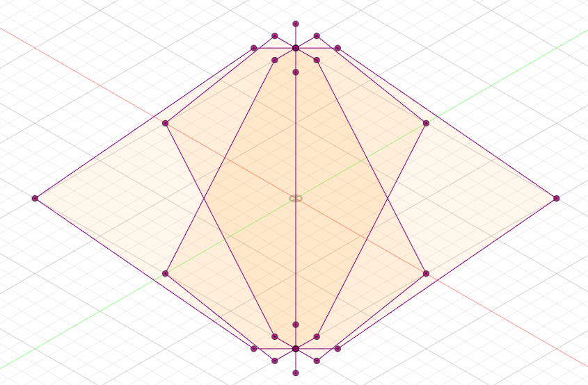
But that shape would also match a double-cone! So we'll need some intermediary photos, in this case, the 45° shot that lies on the plane of (XY-diagonal)Z Plane

Diagonal-Z plane projectionThe traced outlines

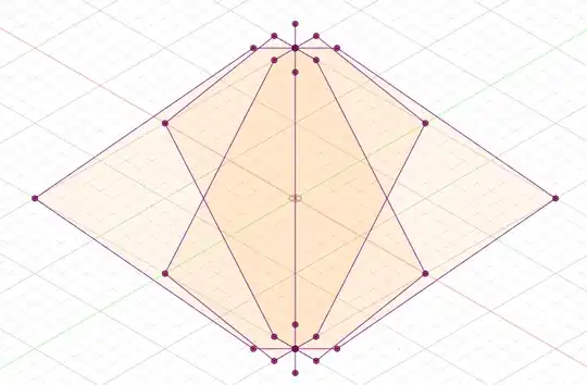
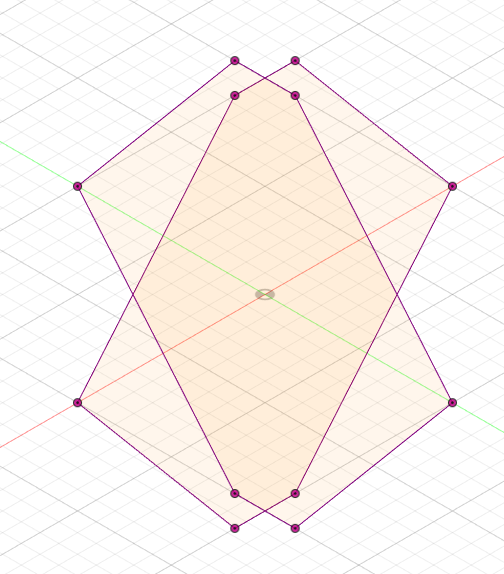
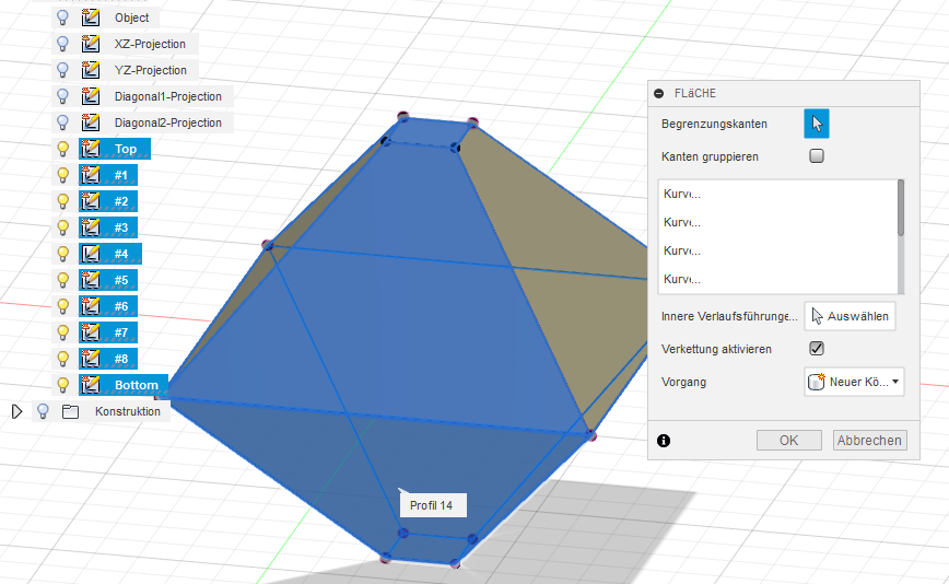
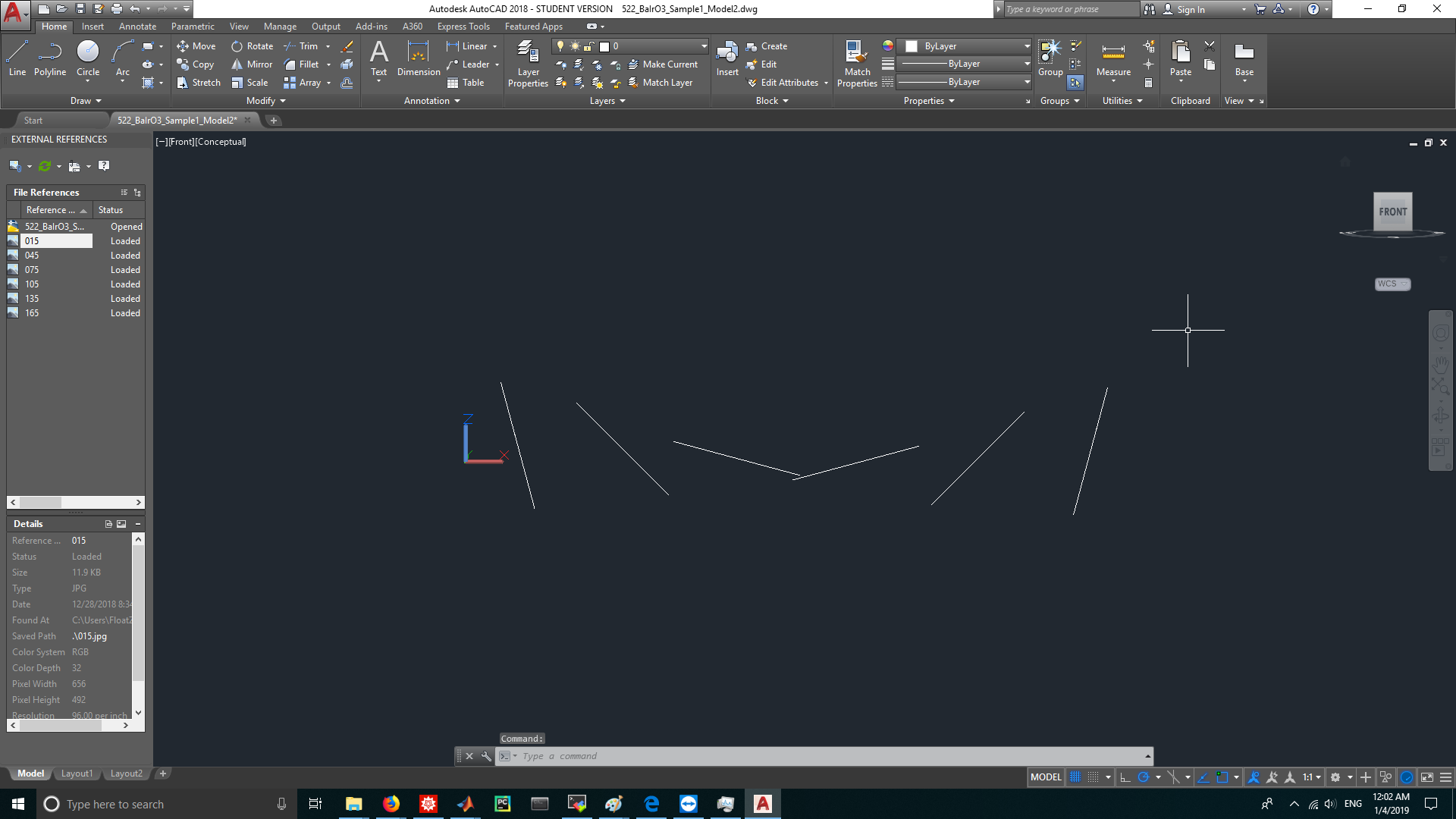
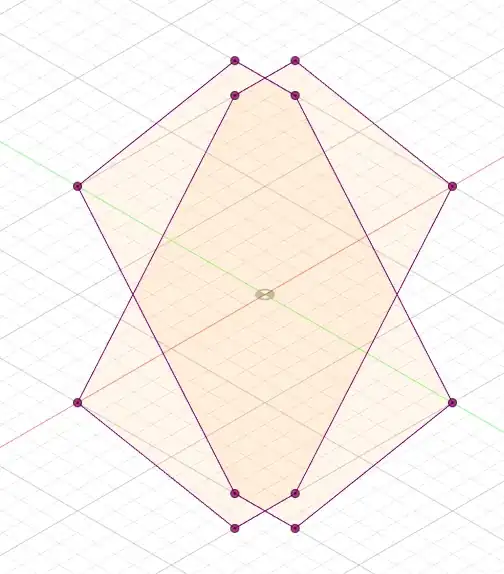
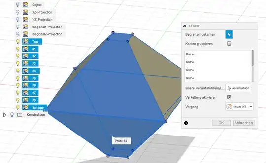
As you see, the more outlines you have, the more detailed the pseudo-body becomes - it is just a gathering of vertices and lines yet though! But, we can take 3 points and create a construction area on these, then draw the face to merge all points on these faces...

construction layers

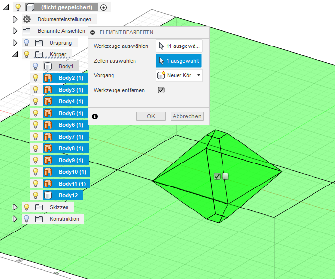
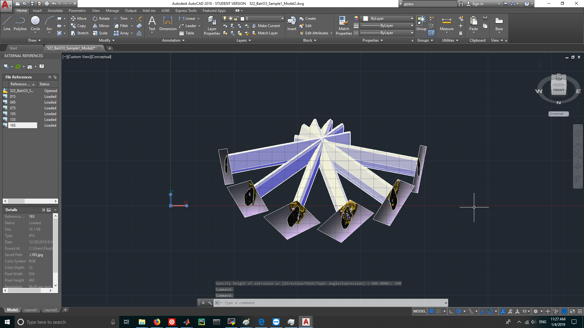
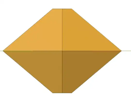
Now, we turn these construction faces into modeling faces, then create a too large object and cut out the whole thing out...

Making the modeling faces Creating the cutout Resulting model

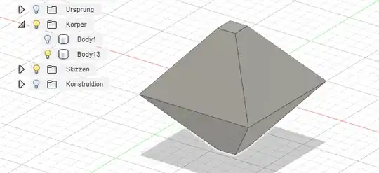
The whole workflow looked like this for 4 pictures (0°, 45°, 90°, 135°)

Workflow

The actual f3D design file is here.

Trish
  • 22,760
  • 13
  • 53
  • 106
3

Inspired by the answer given by @Trish and the following YouTube video, I finally worked out the way to reconstruct the 3D crystal model in AutoCAD.

  1. Import 6 images into AutoCAD. The photos are taken from 6 different angles with 30 degrees separation. enter image description here

  2. Draw 6 lines of length 100 along Y axis in the XY plane. enter image description here

  3. Use ALINE command to align the rotation axis in the photos to the added vertical lines. enter image description here

  4. Use SCALE command to rescale all 6 photos into a uniform size. enter image description here

  5. Use POLYLINE command to trace the cross sections from 6 raster images. enter image description here

  6. Use 3DROTATE command to rotate 6 images and the corresponding rotation axes and traced cross sections along Y axis. The first picture was rotated 75 degrees clockwise when viewed along the +Y axis, the second 45 degrees, the third 15 degrees, the fourth -15 degrees... (Tips: The rotation gizmo will only show in a 3D view. If you didn't see the gizmo, drag the view cube on the right-top to change the view point and try again.) (view from Y axis) enter image description here (view from Z axis) enter image description here

  7. Use 3DMOVE command to move 6 images so that the rotation axis of each image is aligned in a same circle on the YZ plane. (You would need a little bit calculation to finish this step) (view from Y axis) enter image description here (view from Z axis) enter image description here

  8. Use EXTRUDE command to extrude 6 cross sections into 6 cylinders, the height of each cylinder should be long enough so that 6 cylinders will intersect. enter image description here

  9. Use INTERSECT command to get the intersected part from 6 cylinders, this would be the wanted crystal model. enter image description here

1

You may want to do a search for "photogrammetry". This is software that uses many photos to build a 3D model. Dr. Falkingham did a good review of free software on his blog:

https://peterfalkingham.com/2016/09/14/trying-all-the-free-photogrammetry/ https://peterfalkingham.com/2017/12/17/free-photogrammetry-software-review-2017/

His conclusion that works very well for me uses COLMAP to take the photos and build a point cloud, then OpenMVS to build and texture a mesh from the point cloud.

https://colmap.github.io/ https://github.com/cdcseacave/openMVS/wiki/Usage

I have not used many commercial packages, but Pix4D has worked very well for me.

https://www.pix4d.com/

I hope that gets you started.

UrQuan3
  • 111
  • 1