STL is a surface definition
STL is short for "stereolithographic", though I prefer "Surface, TrianguLated". The file only contains the surfaces of an object as triangles, defined by the corners and the direction of the normal vector on each. The dimensions of the file are not saved at all, and in fact, all objects are unitless, as in, the computer knows distances relative to one another compared to a "standard unit", but nothing in the file tells the computer if that unit is 1 meter, 1 millimeter, 1 inch, or 1 arshin.
As a result, the exporting and importing program's settings in what is "a unit" constitutes is relevant knowledge. Often enough this can result in some problems: exporting from a US-setup CAD program gets you the model scaled for inches, while importing into blender expects the unit to be 1 meter, and in most slicers, the expectation for 1 unit is 1 millimeter. But even then, your model might have an arbitrary scale unit, which throws off all expectations.
As such, after importing your model into a modeling surrounding, it might be best to scale the item based on known measurements, and then use the model to make a new model that takes the measurements from the old, but modify them as required.
Over/Re-modeling in CAD
Luckily, the model was saved with 1 unit equalling 1 mm, as measuring the holes, as the 30mm_face.stl indicated. Loading it into Autodesk Fusion360, my CAD package of choice, I was able to measure and re-engineer the item from scratch:
First I positioned one corner in the origin, and created a surface with an angle to the X-axis. From that I learned that the angle of this model to the vertical is 56.3°.

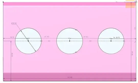
Placing a sketch on that surface, I could measure the outer dimensions as 152.4 mm wide, and 91.58 mm tall. The 3 holes of 30 mm are found at 46.5 mm from the bottom edge, spaced 28.75 mm from the outer edge, and 47.45 mm from each other.
In the back, a pattern of 5 mm mounting holes exists: the lower row of 3 is 4.6 mm from the bottom, the top row is 3.8 mm from the upper edge. Of each set, one is central and the other two are at 23.8 mm from the left/right side edge. Finangeling a little, I found that the mounting holes are 1 mm deep.

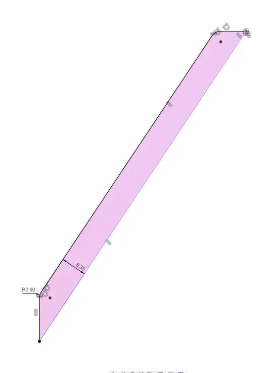
Making another sketch over the side, the front and top edge are orthogonal to the actual box, and the item itself is 6.35 mm thick. The upper and lower corners of the top are rounded at about 2.6 mm.
Extruding from the side to the required width and then punching the mounting hole pattern into the back as a 1 mm extrusion with the two sketches is now trivial.
Taking the row of buttons as a base, it's likewise trivial to design extra holes in appropriate positions with the same diameter. All it now takes is extruding all those holes from the back to the front:
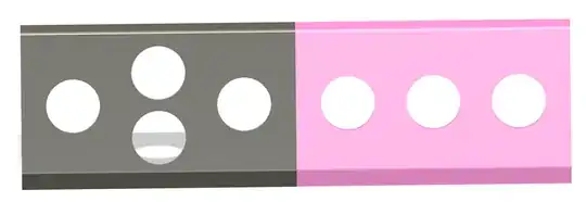

Caveat: the two buttons above one another are, in my model, 6 mm between one another and ~3 mm to the lower round, ~6 mm to the upper round. It would depend on the hardware you wish to mount if that positioning works, or requires further tweaking. A "slanted" central column could be required to create the required clearance to properly mount the hardware.
Dimensioning Note
Technically a "30mm arcade button" exists in two types:
The outer diameter of both items is listed as ~33 mm, allowing the mounting plan above and leaving about 3 mm between buttons.


