I would like to thank @hfcandrew and @MagWeb for their in-depth explanations:
Quoting from the original forum post:
Here's how I do moods from shapes like this needing curved parting lines:

Step: Finding the parting line of the shape:
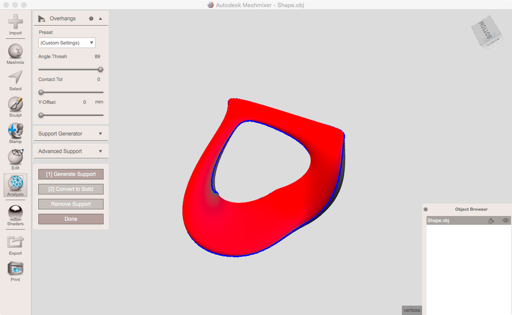
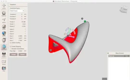
MM's Overhangs shader (drag the sphere with the red bottom onto your object) is pretty useful if it is set to paint regions at its max angle. You can modify this angle in Analysis > Overhangs. Set AngleTresh to max (89°) and cancel the tool. MM remembers this setting to use it for the overhang shader:
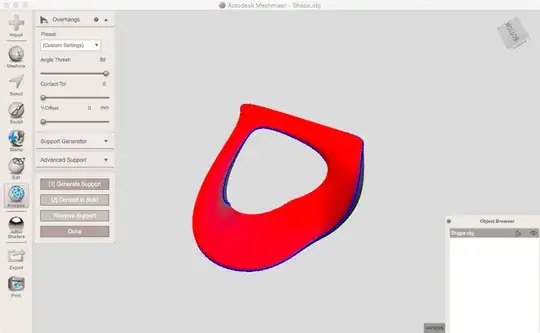
Now drag this shader from Shaders onto your object.
Use Edit > Transform to rotate the object to an orientation where you get a meaningful border of red/white. You want to find a position where there are no white islands within a red area or red islands within white.
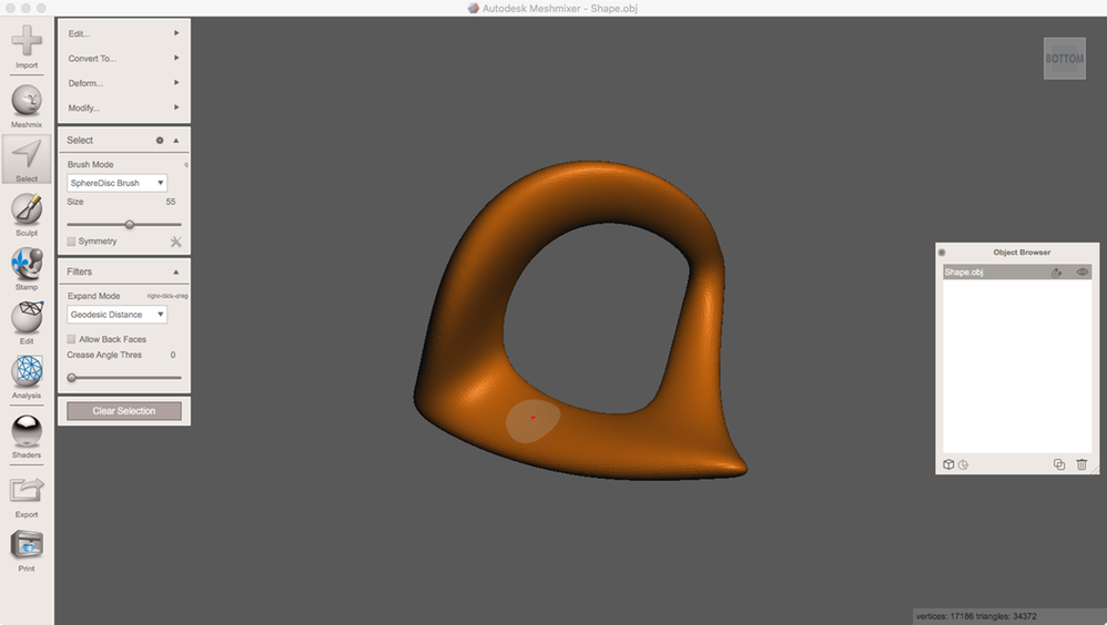
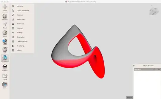
Now using the ViewCube switch to Bottom view. Make sure that you do not navigate for the following: Go to Select, select something (which region doesn't matter at all) and do Modify > SelectVisible:

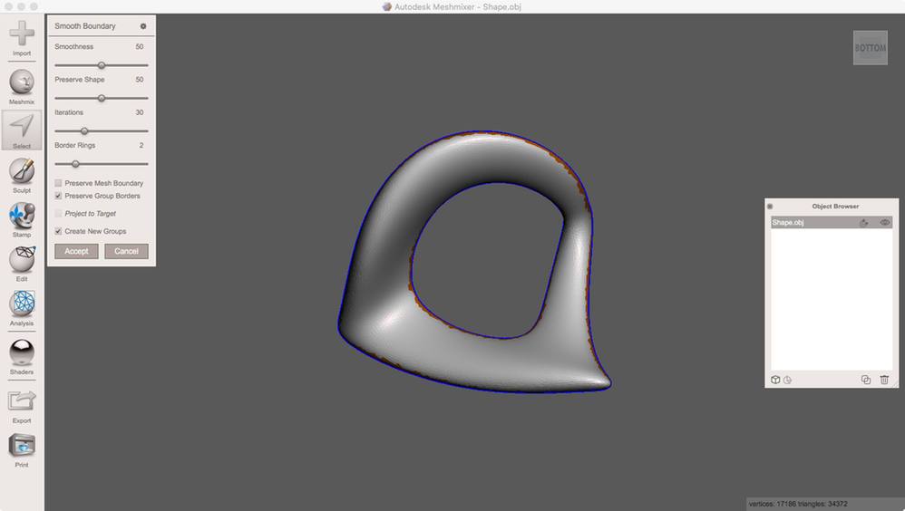
Run Modify > SmoothBoundary. At its default settings, it will create a face group too:
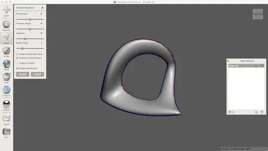
Now you've found the parting line.
- Design a parting surface:
From above you've got a face group. We want to use its boundary to deform a plane primitive:
For easier view drop the first shader from Shaders onto your object.
Go to Edit > CreatePivot. Set PlacementMode to SnapToGroupBorders. Double-click at the group boundary several times to get pivots at that boundary like this:
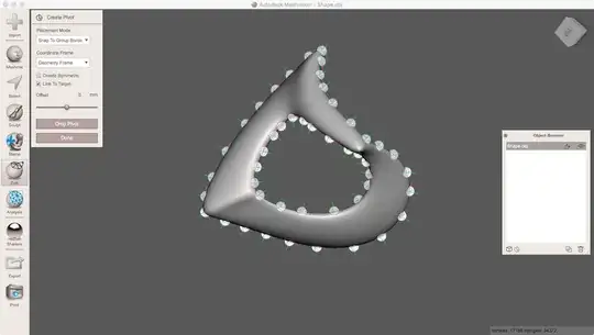
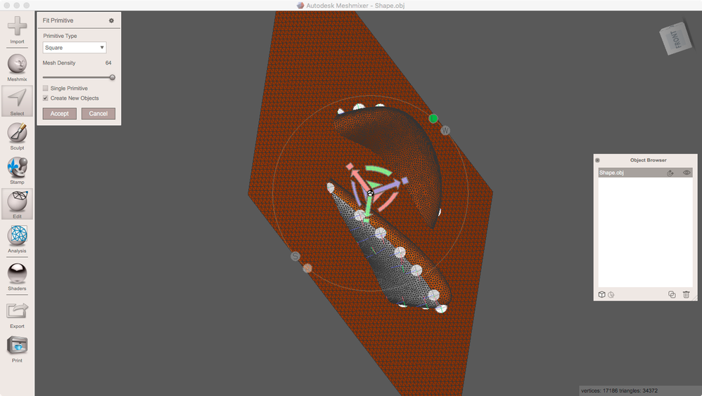
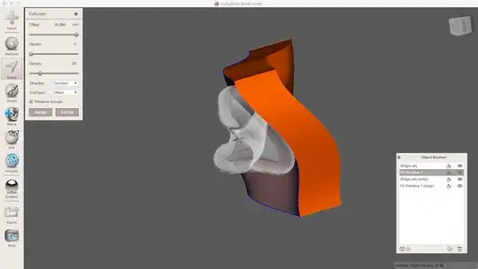
When done go to Select and double-click the face group to select it. Run Edit > FitPrimitive. By default, it will insert a square object. Set a high MeshDensity and make sure to check CreateNewObjects. Scale up the object using the transform widget. It needs to be about two times its fitting size:

Accept. Now there should be a FitPrimitive1 object in your scene. Leave Select and hide the shape object.
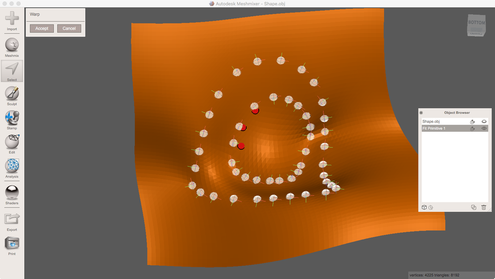
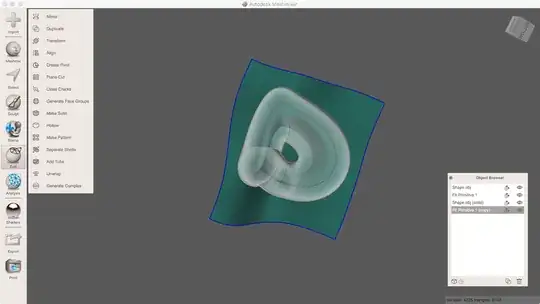
Activate the plane and select all of it (Ctrl/kbd>+A). In Select go to Deform/Wrap.
In Wrap, double-click next to a pivot to create a red sphere. Drag this handle to the pivot to make it snap to it. Do the for all pivots to deform the plane:

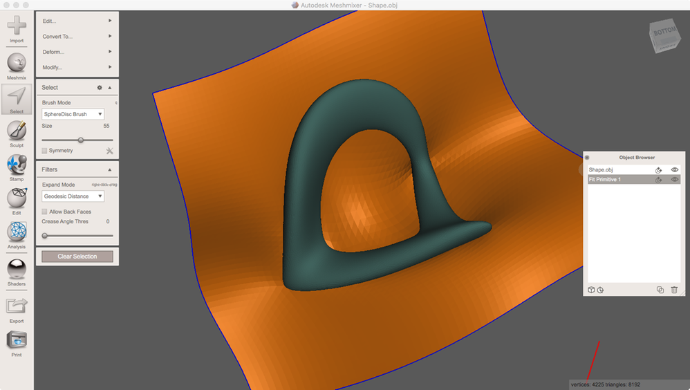
After accepting Wrap, you should discard all pivots. You may make them visible in the ObjectBrowser by clicking the pivot icon in the bottom-left of the browser. You may now show the source shape to check the parting surface:

Next is to construct the molds from that.
- Construct solid molds:
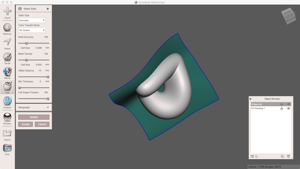
At first, we need to create an offset shell from the source shape. Its OffsetDistance will define the width of the flanges later on. I use Edit > MakeSolid in Accurate mode which allows me to add an offset:

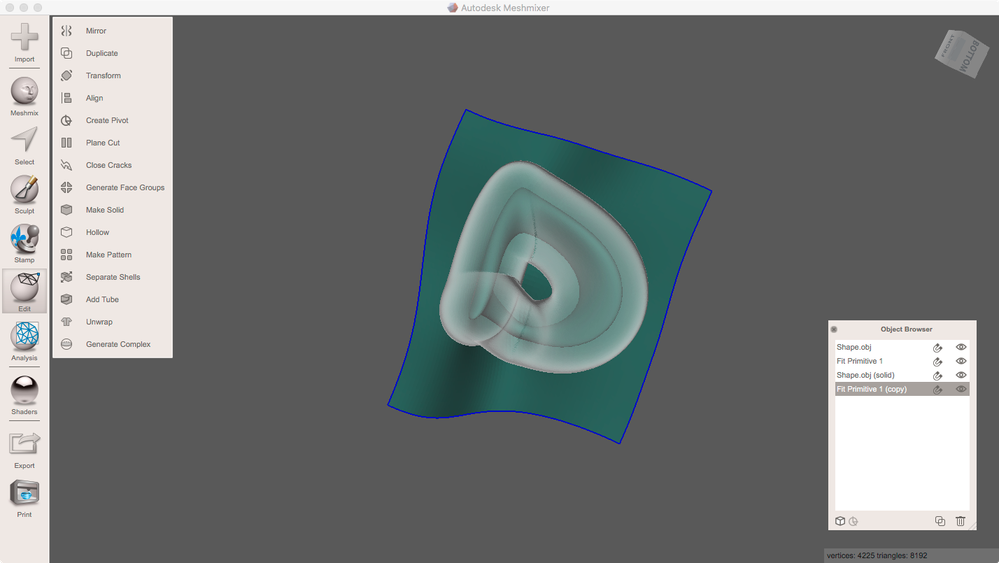
Drag the transparency shader onto this result (top-right in Shaders) and make a copy of the parting surface:
SelectAll of one FitPrimitve an use Select > Edit > Extrude to give it a thickness including the ghost shell to one side.
Do the same on the other FitPrimitive with a negative offset
Make a duplicate of the source shape. Hide all objects but one pair of source shapes and FitPrimitive.
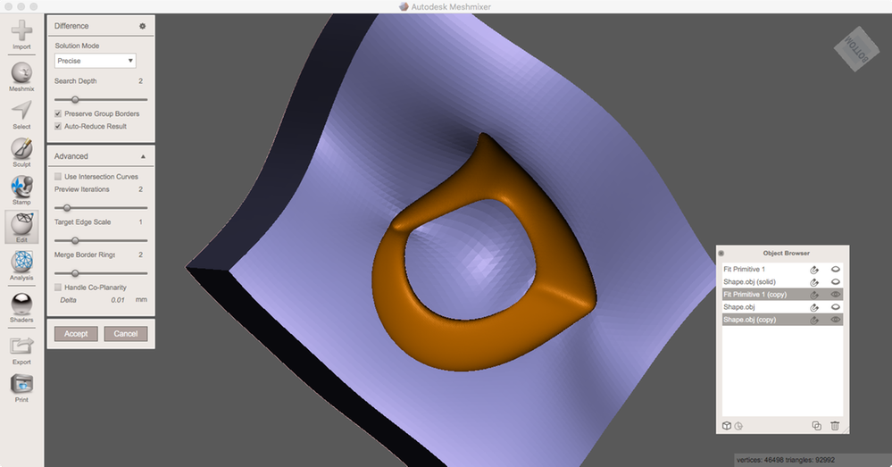
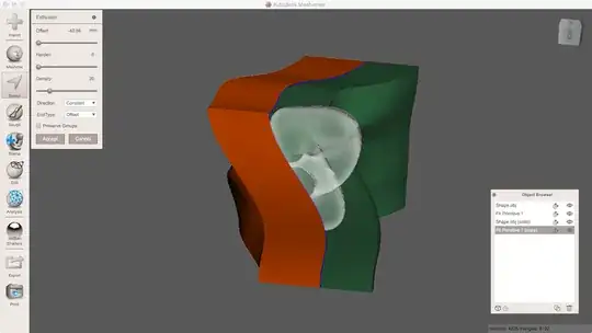
Activate the extruded FitPrimitives as the first and hold down Shift one source shape as the second object. Run BooleanDifference:

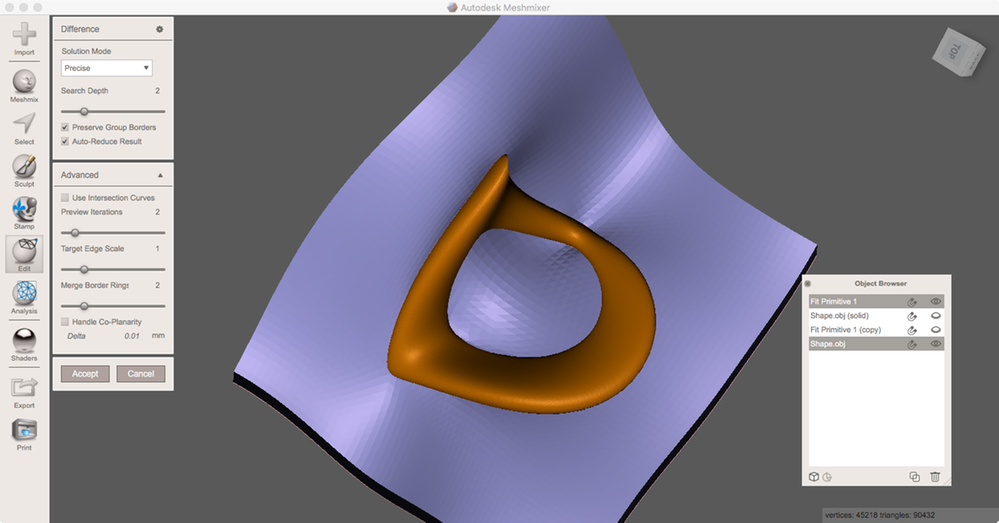
Do the same with the second pair.

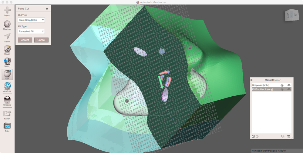
If the molds' sizes are bigger than your printer's volume it's to cut the halves. To do this Edit > Combine both halves to one object for now and run Edit > PlaneCut at Slice(KeepBoth):
Run Edit > SeparateShells to split all of the mold's parts again.
From this point, I modified the technique described for my case.
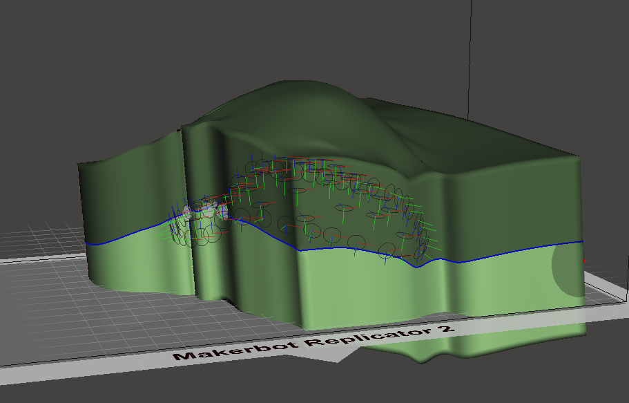
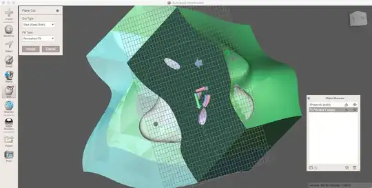
I had to re-mesh and smooth edges quite a few times in Meshmixer to obtain a completely solid object without any holes, which enabled me to make a boolean difference.
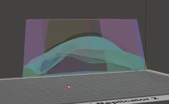
Here is my re-meshed bone and the plane cutting through it:
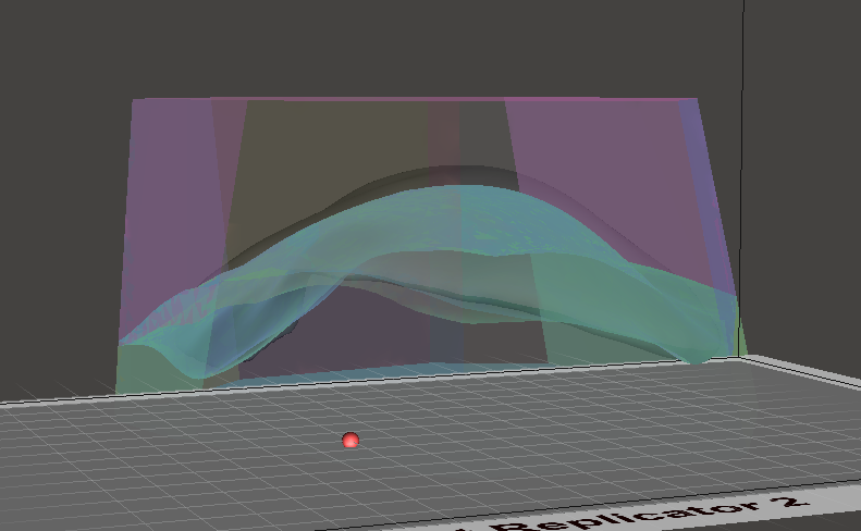
I made two copies of the fit primitive, and extruded them in separate directions:

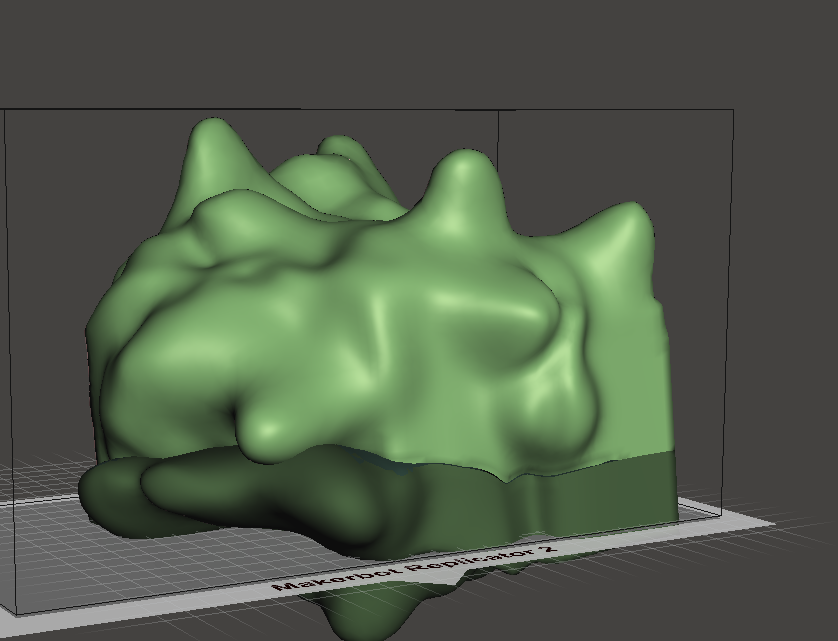
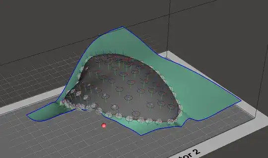
While this is not an elegant solution, I sculpted each mold piece to have a thicker mold that I can cut into orderly pieces, so I can print and compress the bone cement in between.

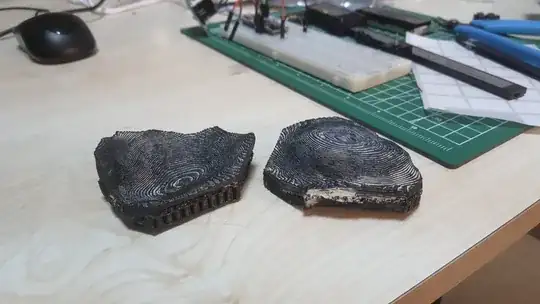
I cut a few planes through the mold, obtaining this orderly shape.
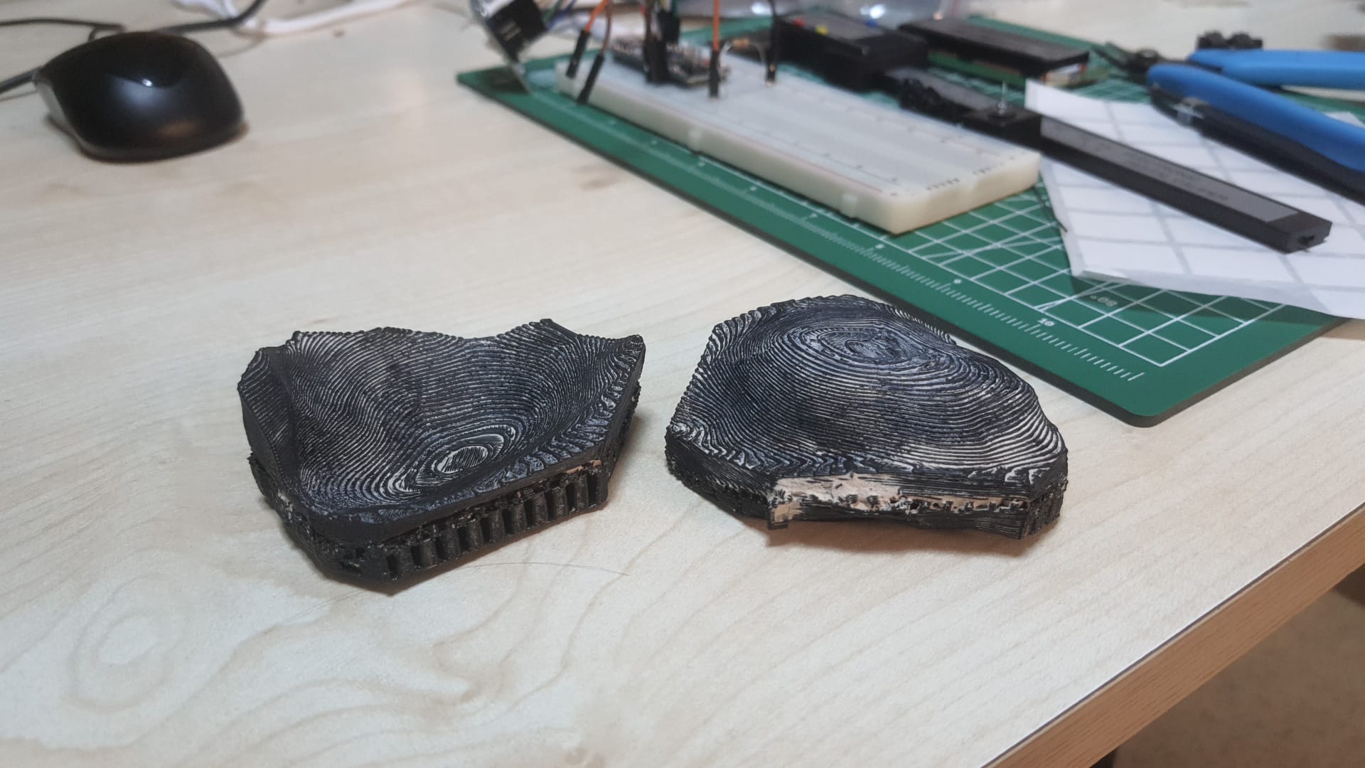
Now to print it:
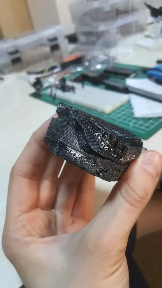
Obviously, it would be better to create some mechanism to improve alignment(Ball/hole or some pins?).
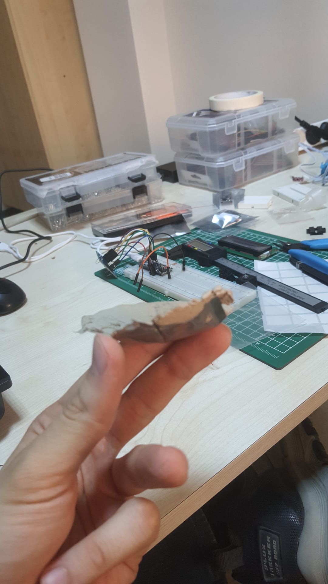
But here is the end product, not dried yet: