Firts of, I created a quick simplified simulation in Matlab of cooling from 210°C to bellow 50°C. Here is a plot showing the difference in temperature curves in time. As stated, it is simplified, because I guessed that a printed piece can get from 210 deg to 50 in less than 5 seconds when cooled properly to room temperature.
I used this differential equation:
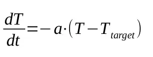
where T is temperature, t is time, T_target is target temperature (temperature of cooling air), a is a constant which I adjusted to meet the above specified criteria (a = 0.5)
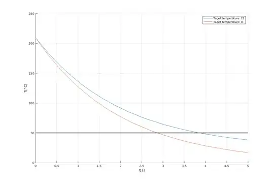
As you can see, you save about a second of cooling time. You say whether it is enough. In my opinion it is irrelevant for standard printing.
Here is the Matlab source code if you want to try and experiment with it (it might run in GNU Octave as well, but I haven't tried it):
clear;
clc;
a = 0.5;
targetTemp1 = 23;
targetTemp2 = 0;
tempLine = 50;
timeSpan = [0, 5];
x0 = 210;
[t1, y1] = ode45(@odeFcn, timeSpan, x0, 0, a, targetTemp1);
[t2, y2] = ode45(@odeFcn, timeSpan, x0, 0, a, targetTemp2);
figure("Position", [360, 1220, 1200, 800]);
hold on;
plot(t1, y1);
plot(t2, y2);
plot([timeSpan(1), timeSpan(end)], [tempLine, tempLine], "Color", "black", "LineWidth", 2);
grid on;
legend("Taget temperature: " + targetTemp1, "Taget temperature: " + targetTemp2);
xlabel("t[s]");
ylabel("T[\circC]");
function y = odeFcn(t, x, a, target)
    y = -a * (x - target);
end
That being said, here is how I calculated the needed pressure.
Constants:
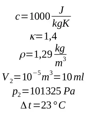
c is specific heat capacity of air, κ is Poisson constant for air, ρ is density od air, V_2 is volume at atmospheric pressure, I estimated this value, Δt is temperature difference assuming the pressurized air is at room temperature and need to be cooled down to 0 degrees
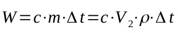
The needed energy too cool the air by delta t is given by this formula:
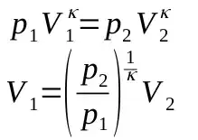
And assuming this is adiabatic process with ideal gass, we can use this equation to find p1:
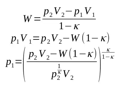
assuming V1 is given by:
I calculated the needed work W is 0.3 J and the pressure p1 is 148 kPa. To me this seems fairly low, I might have made a mistake somewhere or a wrong assumption. However, I would always suggest experimenting and finding an answer empirically, because there are too many unforseen variables like: air humidity, parts that would absorb/release the heat, direction and speed of the airflow, crossectional area of the outlet and so on.
Hope this helps.
[Edit] You can find the equations on wikipedia here and here. Sadly, it is in Czech, because the English variant does not have the equations in this format.


