7

For practicality sake, I need to print a design such that there will be weight hanging parellel to the layer lines. Is there an infill pattern that would be better than others at handling this?

I realize that all kinds of infill will still have the same layer boundaries. Just wondering if choosing any given infill might provide better results.

linuxdan
  • 1,423
  • 2
  • 15
  • 28
  • 2
    CNC-Kitchen anyone? – Trish Feb 11 '20 at 11:06
  • 1
    If your layer lines are a concern for strength, different infill patters won't help because they are on the same layer lines (as you suggest). Your best bet is to reconfigure the print so the layer lines are no longer an issue, or consider creating the object using a different medium. Sometimes "practical" doesn't get the job done. If the part doesn't work, it doesn't make your life any easier :o) – Pᴀᴜʟsᴛᴇʀ2 Feb 11 '20 at 12:48
  • Wondering if it's possible to designate "spiralization" for infil independent of the structure's walls? But I agree with paulster that you should consider reorienting the print so the layers are perpendicular to the hanging mass. Alternatively, make the part into 2 or more pieces so as to achieve desired layer orientations. – Carl Witthoft Feb 11 '20 at 16:00

3 Answers3

3

Yes, some infill patterns are better than others for preventing separation of layers. Basically (modulo some assumptions about uniformity of distribution of force), the shearing strength of the part in the Z direction at a particular layer is going to be proportional to the surface area of bonding between successive layers. So infill patterns that stack identical infill extrusions on top of each other at each layer should be expected to be much stronger than patterns where successive layers make only partial contact. In other words, "2D infill patterns" - grid, lines, triangles, tri-hexagon - should be a lot stronger than "3D infill patterns" - cubic, octet, gyroid, ... This matches my experience printing bolts oriented along the Z-axis - ones printed with gyroid snap easily unless other measures are taken to strengthen them, while ones printed with triangles are fairly strong (though nowhere near as strong as ones printed oriented in the XY plane.

If you have other reason to prefer a "3D infill pattern", its weakness can be mitigated mostly by increasing the infill line width, so that the lines of successive layers which don't entirely overlap still touch on more surface area. (Just increasing the infill line width also works to make "2D infill patterns" even stronger.) However, be aware that with high print speed typically used for infill, increasing infill line width can easily exceed the capability of your hotend, resulting in underextrusion, extruder skipping, and stringing all over the place.

1

The shearing strength characteristics, or better known as interlaminar shear strength (ILSS) characteristics, describe the shear strength between the layers. This is also known as flexural or bending strength characteristics. These are best obtained by performing a 3- or 4-point bending test; these tests are standardized by the American Society for Testing and Materials, ASTM International (e.g. ASTM D 7264).

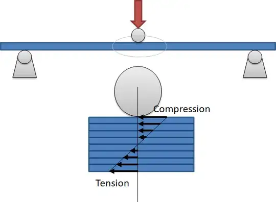
The bending test will cause internal compression (concave side during testing) and internal tension stresses (convex side during testing). The figure below shows the general setup of a 3-point bending test and below that magnification of the stresses inside the test specimen.

enter image description here

The tests concern the interlaminar shearing of layers, so, the much more material a layer consists of (e.g. infill percentage) the higher the resistance against shearing off. Also, how the infill is internally supported by its form helps, if it buckles easily on the compression side, the buckling occurs before shear off.

Not only the type and percentage of infill is important for the flexural strength, but also the layer height, nozzle diameter print temperature as found in this research paper. Another paper, "Effect of infill on tensile and flexural strength of 3D printed PLA parts" directly answers your question, quoting the figure from the paper:

enter image description here

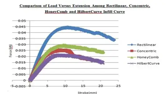
You should choose an infill that has the most support. Since year and day, in creating composite sandwich panels (often used in aerospace applications where high stiffness and low weight are essential) honeycomb core structures are used as these honeycomb structures allow minimization of the amount of weight and used material. From the figure above you see that rectangular infill is best suited for FFF products. Honeycomb is the second best, but significantly lower. Note that orientation is key! E.g. this test conducted by Martin shows that Gyroid and honeycomb infill performs better than rectilinear:

enter image description here

To answer your question, not only infill pattern, but also infill density, nozzle diameter, layer height and orientation play an important role in the shearing strength. This is why ASTM has defined a standard so that we can compare results amongst different materials or different lay- or set-ups. These tests are typically performed dynamically (alternating load), statically with increasing load (increasing load with time) or statically fixed load (constant load to determine the creep properties, these test typically take a long time when the load is low).

0scar
  • 37,708
  • 12
  • 68
  • 156
0

0scar's answer is the "solution" or true answer to the question.

Watching youtube the last few days, cubic needs to be considered. I was surprised at what I saw. More to consider is adding design elements:

  • The concept of flutes along the perimeter.
  • Adding through holes increases strength incredibly.
Krista K
  • 131
  • 4