7

I am using LightBurn to laser engrave on wood. I am just trying to print some letters.

In the softwares preview the output looks correct. The black part is where the laser should burn and the red part are traversal/scan lines enter image description here

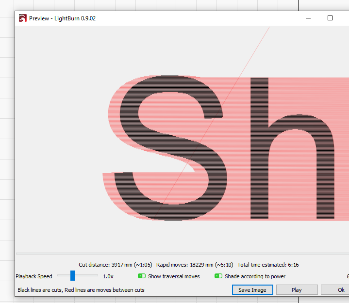
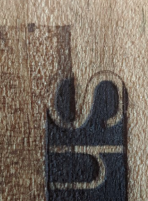
When i actually print it the negative space is burnt by the laser (basically where the traversal/scan lines are shown in the preview above)


What I was able to figure out is that:

  • M42 P4 S255 properly turns on the laser when I send this command on its own,
  • M42 P4 S0 properly turns off the laser.

But the issue is when I send the following G-code, the following happens:

M42 P4 S255 <--- Laser turns on for a flash of a second
G1 X15 <--- By the time the movement starts the laser is already off.
M42 P4 S0

When i stopped using PWM (via the D11) and instead connected directly to D9 (which is for the fan) this issue stops occurring. So this issue is only occurring when I use PWM. Any Guidance on what to check

Update: I read the following on another forum. This might be the root cause here.

M42 is an immediate command and would turn on the laser before it reached its intended start point, M106 and M107 are buffered so the on/off can happen in its intended locations.

codeNinja
  • 183
  • 1
  • 8

2 Answers2

5

M42 command is an immediate command. This means that it will run before the move GCode commands finish. This is exactly what I was facing.

This video has the walk-through of solving the issue:

Here is the relevant PDF it talks about: The 2.8 watt, $100 Laser Upgrade for MPCNC.

Here is the relevant section on page 7 of the PDF:

  1. The laser driver requires a 5 volt TTL input control signal. The Marlin fan control Mcodes (M106 and M107) will be used to control the laser .Unfortunately, the Ramps fan output (D9) is a 12 volt signal so we can’t use it. We'll need a quick firmware edit to remap the fan output from pin D9 (12v) to pin 44(5v).

  2. Make a backup copy of your Marlin firmware folder first. Open the pins_RAMPS_13.h file in your Marlin firmware folder with a text editor (Wordpad). Search for the line where the fan pin is assigned and change it from pin 9 to pin 44.

  3. Save the changes and flash the revised firmware back onto your Mega board.

T.J.L.
  • 158
  • 11
codeNinja
  • 183
  • 1
  • 8
4

This is too long for a good comment but may fall short of being a true answer. If the mods prefer, I can recast it as a set of comments.

There are several differences between using a GPIO pin as a binary data pin and using one as a PWM pin, and the behavior depends on several factors:

  1. Is the PWM pin a native PWN pin with hardware support, or is the PWM function being implemented with software?
  2. Has the PWM pin been initialized as a PWM pin?
  3. What processor type is used?
  4. What is the PWM frequency?
  5. Is the pin a TTL compatible output [0.4 V low, 2.7 V high]? CMOS? What Vcc?
  6. For that matter, what is the CPU?

As @0scar points out, the fan control pin is typically not connected directly to the fan, but instead uses a FET to provide isolation and switch more current than the output pin can provide. Depending on the circuit, it may be inverting or non-inverting. M42 Pxx S255 may be full on or full off. When the fan is controlled through the fan G-code, the firmware can take possible inversion into account.

You haven't said what the input circuit to the laser involves.

  1. It is active high or active low?
  2. Does it require a pulse train to keep the output on, or is it static? I don't know how yours works, but I could imagine designing a laser module to require a continuous stream of pulses to keep the beam active so that a failure in the drive circuit could not create a safety hazard.
  3. Is it a TTL compatible input [0.7 low, 2.4 high]? CMOS? What Vcc?
  4. Is it something else?

Laser etching is generally on-topic for this group given the close association with 3D printing tech, but people are less familiar with the "standard systems". For some of us to be helpful (especially for me to be helpful) we need more of the circuitry and firmware context.

0scar
  • 37,708
  • 12
  • 68
  • 156
cmm
  • 4,591
  • 14
  • 37